+91 7710052533
sales@orbitalautomation.com
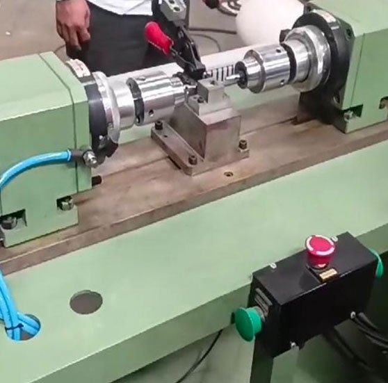
BTM offer you sheet metal machine, sheet metal clinching, metal clinching likes Tog-L-Loc, the sheet metal clinching technology that is simple, economical and an efficient solution to your metal joining needs.
Years Experience

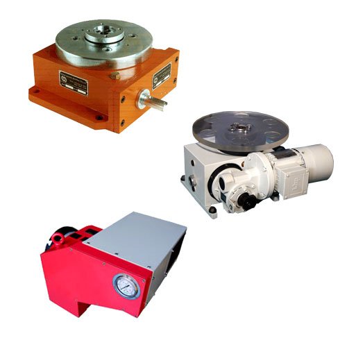
We are now the market leaders in India in Riveting Machines, Index Table, Clinching Machine and Assembly Automation. Orbital systems works are at Mumbai, Thane & Nashik. Today we have a team of 150+ people with an experienced team of Design Engineers, Electrical Engineers, PLC Programmers, Assembly Engineers, Sales and service team, Marketing team & an in-house precision manufacturing setup.

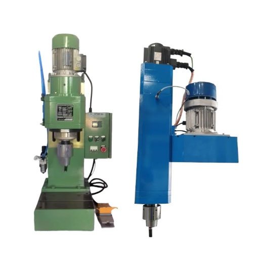
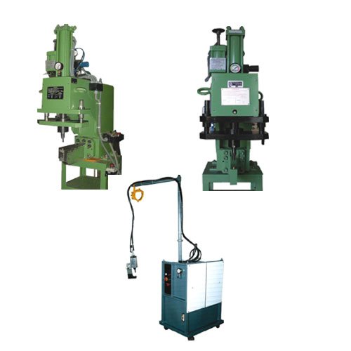
We specialize in providing advanced Riveting Machines for a wide range of industrial applications.
We offer advanced Clinching Machines that provide fast, reliable, and cost-effective joining solutions


Orbital System (Bombay) Pvt. Ltd. invites you to redefine the assembly automation landscape through strategic Joint Ventures (JV). With decades of experience, cutting-edge solutions, and global market access, we offer the perfect opportunity to collaborate and innovate.
+91 7710052533
sales@orbitalautomation.com
F-19, Street No. 18, MIDC, Satpur, Nashik - 422 007, India.